Line Scan Palmprint Recognition System
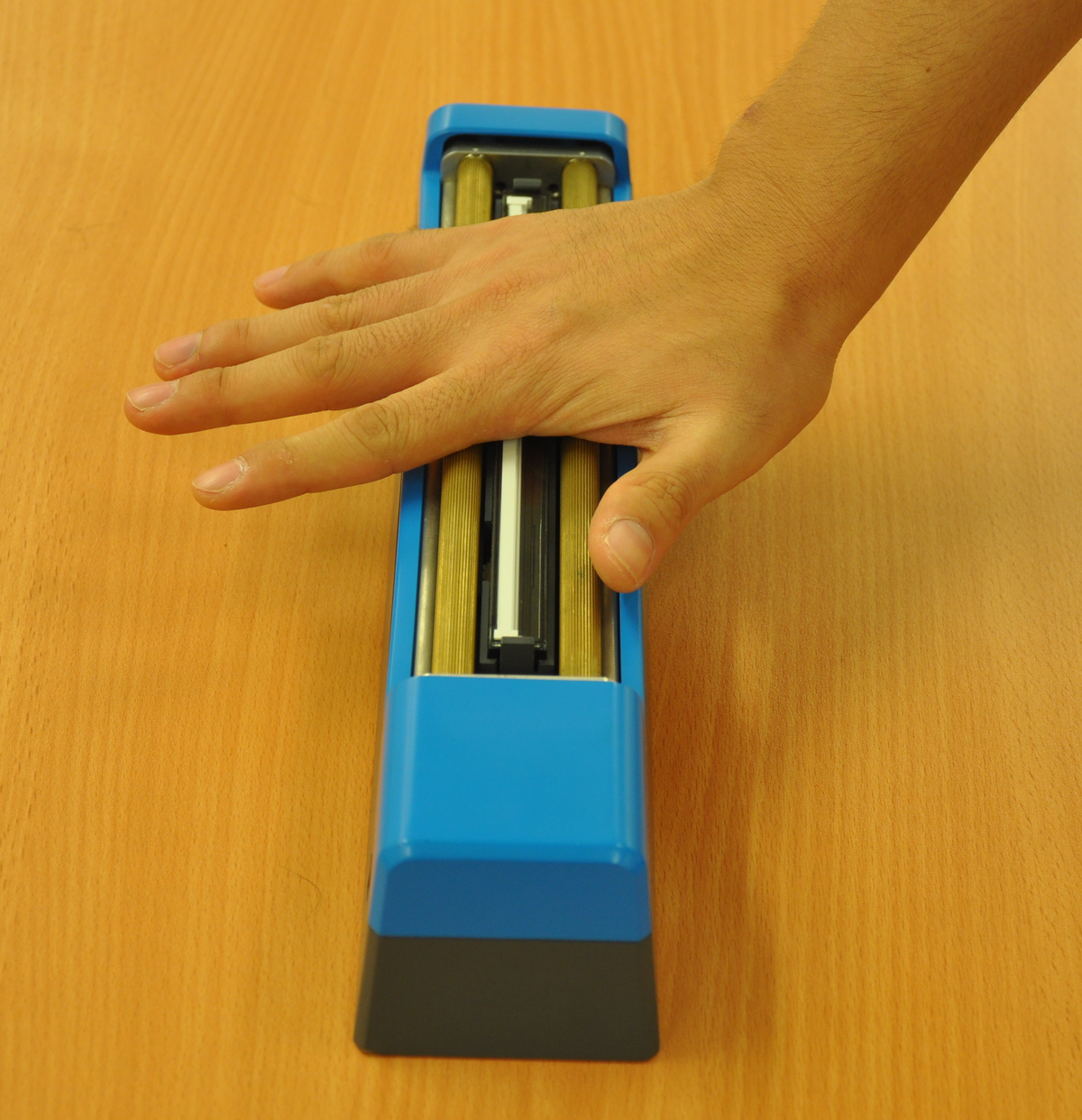
Demo
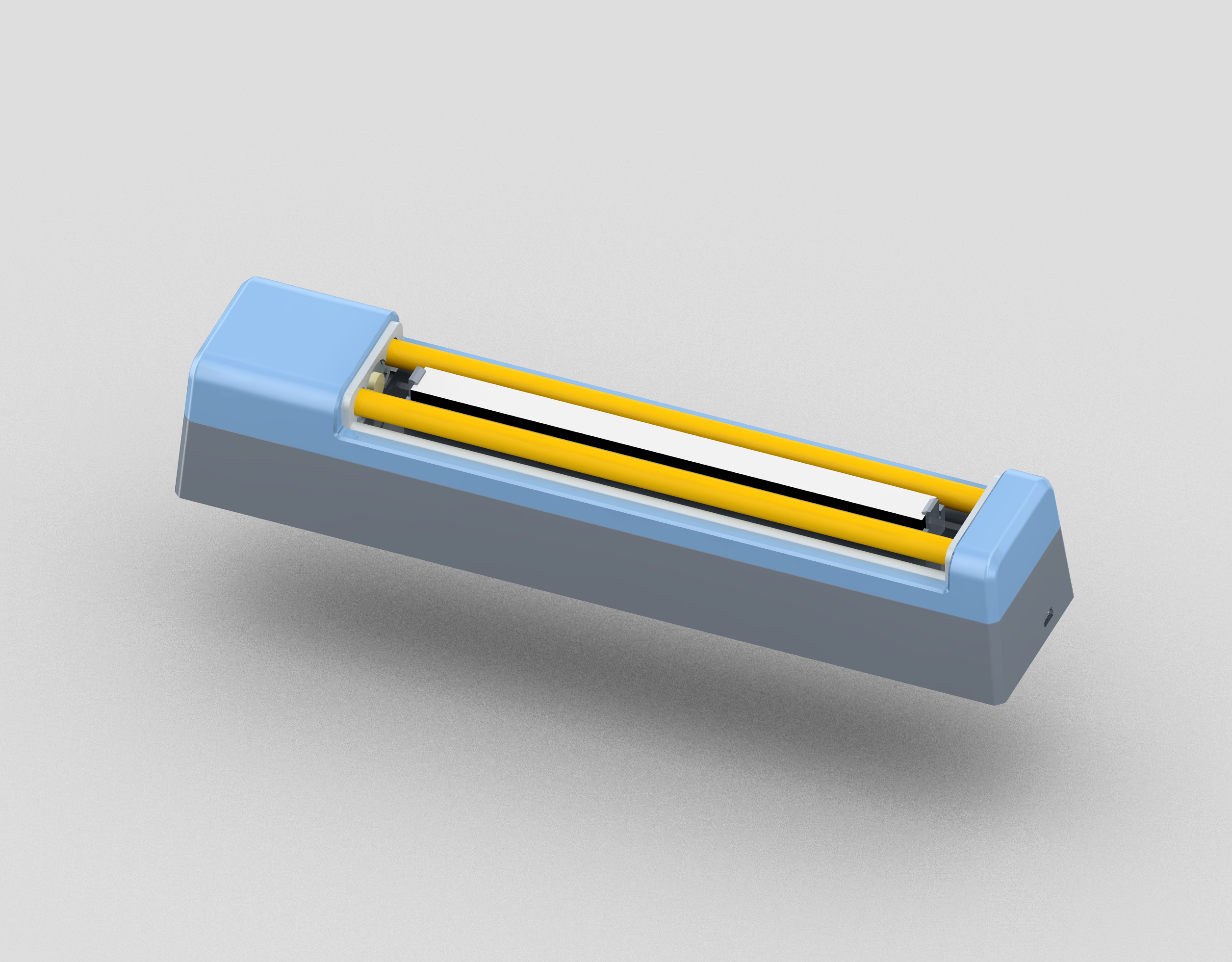
Sensor
System
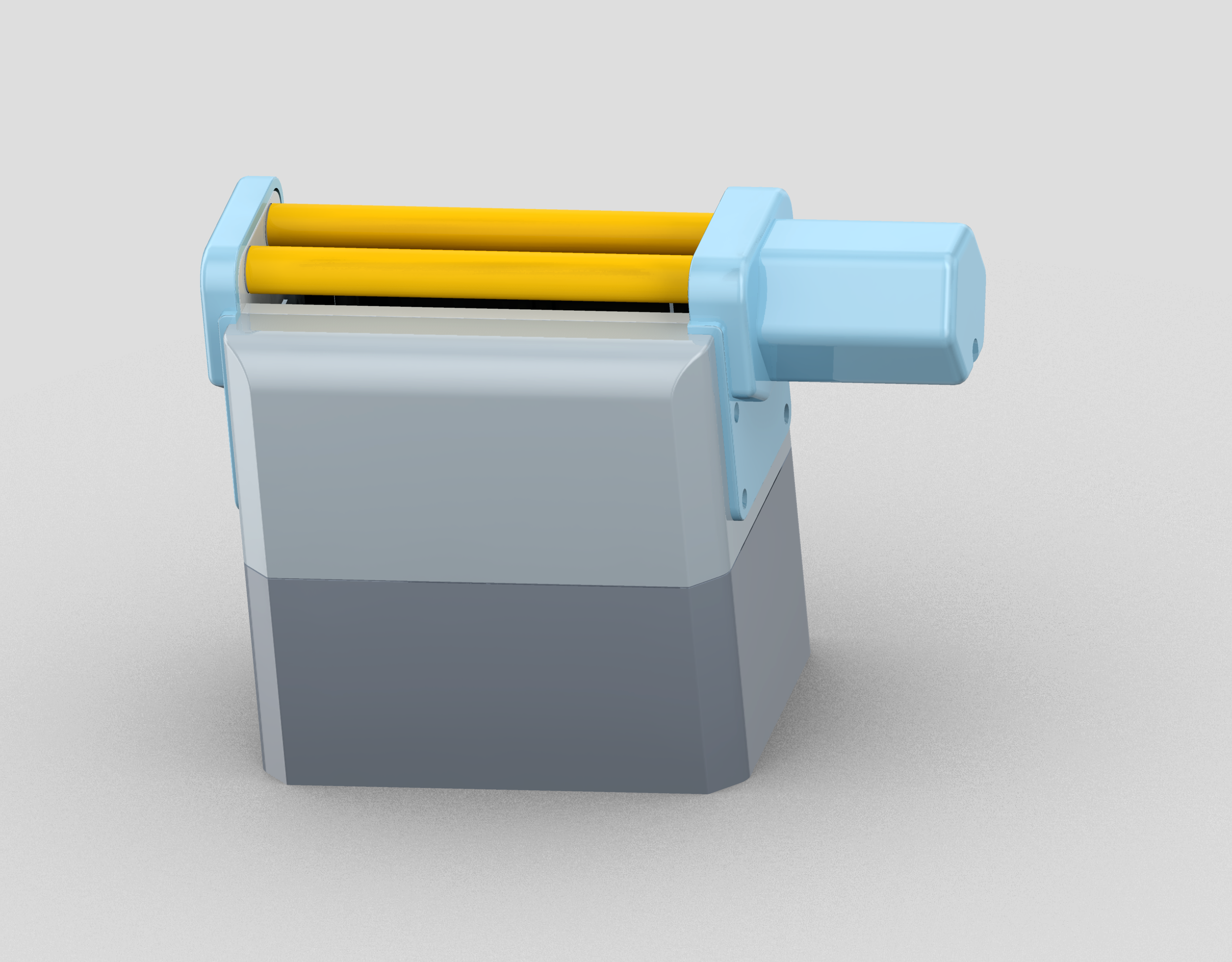
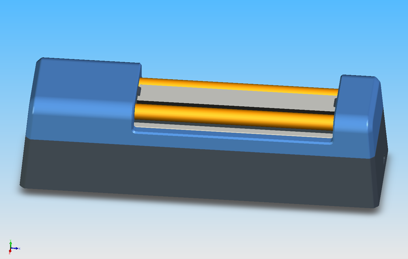
Synchronizing Unit
The motion on the rollers is digitized by the photoelectric encoder to send out synchronizing pulses through the gear set. The image resolution on the motion direction is defined by the rollers and the gear ratio.
Given a gear ratio, \(R_g\), and the diameter of rollers, \(D_R\), when the hand moves \(M_R=\pi D_R\), the roller rotates one round. Then the axis of the encoder rotates \(R_g\) rounds. If the encoder sends out \(P_e\) pulses per round, the encoder sends out \(P=\frac{P_e}{R_g}\) pulses for \(R_g\) rounds. It means that when the hand moves \(M_R\) mm, the encoder sends out \(P\) pulses. For a filter ratio \(R_f\), the sensor only captures \(\frac{P}{R_f}\) lines, then the resolution \(S_M\) (in metric) can be computed by dividing the number of captured lines \(\frac{P}{R_f}\) by the distance \(M_R\), as follows:
Here, the unit of the \(S_M\) is lines per mm. One inch is 25.4 mm. Thus, the resolution \(S_L\) (in dpi) can be defined as following equation.
In our prototype device, the photoelectric encoder is industry standard at 500 pulses per round (\(P_e=500\)). The rollers’ diameter, \(D_R\), is 10 mm. The gear ratio \(R_g\) is \(2 : 1\). The filter ratio \(R_f\) is \(2 : 1\). Under this condition, the vertical resolution (along the rolling direction) is 101.1 dpi, which is close to the resolution along the width direction of the CIS module (100 dpi).
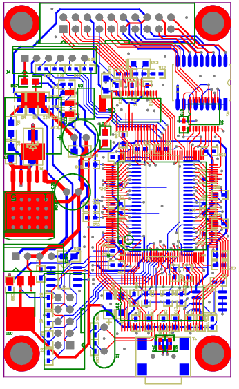
FPGA Board

Future Applications
Publications
Journal
- Qu, Xiaofeng; Zhang, David; Lu, Guangming, “A Novel Line-Scan Palmprint Acquisition System,” in Systems, Man, and Cybernetics: Systems, IEEE Transactions on , vol.PP, no.99, pp.1-11.
Patent
A Human Palmprint Image Collection Apparatus and A Processing Method (in Chinese)
- Grant
- China Patent Number: ZL 2011 0362063.8
- China Patent CN102521584 (A) / CN102521584 (B)