A Novel Line-Scan Palmprint Acquisition System
Xiaofeng QU, David ZHANG, and Guangming LU
Qu, Xiaofeng; Zhang, David; Lu, Guangming, “A Novel Line-Scan Palmprint Acquisition System,” in Systems, Man, and Cybernetics: Systems, IEEE Transactions on , vol.PP, no.99, pp.1-11.
Abstract
Biometric recognition systems have been widely used globally. However, one effective and highly accurate biometric authentication method, palmprint recognition, has not been popularly applied as it should have been, which could be due to the lack of small, flexible and user-friendly acquisition systems. To expand the use of palmprint biometrics, we propose a novel palmprint acquisition system based on the line-scan image sensor. The proposed system consists of a customized and highly integrated line-scan sensor, a self-adaptive synchronizing unit, and a field-programmable gate array controller with a cross-platform interface. The volume of the proposed system is over 94% smaller than the volume of existing palmprint systems, without compromising its verification performance. The verification performance of the proposed system was tested on a database of 8000 samples collected from 250 people, and the equal error rate is 0.048%, which is comparable to the best area camera based systems.
1 Introduction
Biometrics, led by the fast development of imaging technologies and pattern recognition algorithms, has been utilized in complicated fields, from physical/logical access control to justice/law enforcement; from time and attendance to health care biometrics (Jain and Feng, 2009, Laadjel et at., 2009, Dai and Zhou, 2011, findbiometrics.com). Now, the requirements of biometric systems do not only focus on a high recognition rate and robustness, but have also extended to compact, online, user-friendly, and flexible for complicated cross-disciplinary applications. For instance, hand-held fingerprint capturing devices and iris capturing devices are widely used for outdoor applications. Fingerprint sensors being integrated with laptops, fingerprint sensors being embedded in locks, iris sensors being integrated with the steel safe provide better user experience and higher security than conventional solutions. However, one of the best biometric technologies, palmprint recognition, which exhibits excellent recognition performance for the rich feature and is highly reliable under multi-spectrum light, has displayed limitations in these new features. Because of the limitations of current palmprint acquisition systems, especially the dimension of the device, the application of palmprint recognition systems is limited. For example, current palmprint recognition systems are too large to be embedded into a conventional door, and have to be installed beside the door as a standalone device.
The first online palmprint identification system was invented in 2003 (Zhang, 2003a). Since then, numerous acquisition systems have been created, such as flatbed scanners capturing pressed palmprints (Ong, 2003, Han, 2003, Connie, 2005, Lin, 2005, Goh, 2006, Badrinath, 2007, Zheng, 2007a, Struc, 2008), web camera based systems (WCBS) capturing unconstrained palmprints (Shu1998, Kumar2003, Han et al., 2007b, Goh et al., 2008, Chaudhary2009, Zhu and Zhang, 2010, Ong2010, Aykut2013, Genovese2014), and palmprint acquisition systems with the pegged flat platen surface capturing stable palmprints (Kong2002, Zhang2003a, Kong2003, Wong2005, Kong2006, Hao2008, Wang2008, Kong2009, Li2009, Zhang2009, Zhang2010, Zhang2010b). These systems achieve good recognition performance. However, being limited by the imaging structure, the device dimensions of these systems cannot be reduced further. In addition, user interactions and applications were also limited by the size and the structure of the systems. For example, most palmprint acquisition systems are large, and can only be used as desktop or standalone devices.
Line-scan technique would be an ideal solution for a palmprint acquisition system. Using the line-scan technique, palmprint-capturing devices could save a great amount of space for a comfortable user interface and flexible structure without sacrificing image quality and system performance. In a line-scan sensor (also called the linear image sensor, the one-dimensional image sensor), pixels are placed in a linear array, which is different from area sensors. Because of this layout of the pixel array, the imaging structure can be simplified, and space can be saved.
The contributions of this paper are as follows.
- We propose a novel palmprint acquisition system, which uses a line-scan sensor, specifically a contact image sensor (CIS) module. The proposed system is 94% smaller than area sensor based solutions.
- In the proposed CIS based palmprint acquisition system, a novel synchronizing unit is designed to solve the motion synchronizing problem, which occurs when using a line-scan sensor in a palmprint acquisition system. With this unit, a CIS module could capture palmprint images adaptively when a hand rolls through the rollers.
- The proposed palmprint acquisition system is evaluated on the merit of verification performance, with the help of conventional region of interest (ROI) extraction method and competitive coding scheme feature extraction method. The verification performance of the proposed system is comparable with current area-based ones, which is supported by the experiments on a database of 8000 images from 250 people.
This paper is organized as follows: Section 2 reviews existing acquisition systems. In Section 3, the details of the structure and each component of our line-scan palmprint acquisition system (LPS) are presented. In Section 4, the system performance is evaluated by verification experiments. Comparisons between the proposed system and area-based systems are also presented here. Section 5 concludes this paper.
2 Existing Systems
There are three different kinds of palmprint acquisition systems capturing palmprint images in different conditions: Flatbed scanners capture pressed images (Ong2003, Han2003, Connie2005, Lin2005, Goh2006, Badrinath2007, Zheng2007a, Struc2008). Systems with a digital camera or a web camera that capture unconstrained images (Shu1998, Kumar2003, Han et al., 2007b, Goh et al., 2008, Chaudhary2009, Zhu and Zhang, 2010, Ong2010, Aykut2013, Genovese2014). Systems with a pegged flat platen surface that capture stable images (Kong2002, Zhang2003a, Kong2003, Wong2005, Kong2006, Hao2008, Wang2008, Kong2009, Li2009, Zhang2009, Zhang2010, Zhang2010b).
2.1 Flatbed Scanner
A flatbed scanner captures contact palmprint images in high resolution. It has been utilized as a palmprint scanner by many researchers (Ong2003, Han2003, Connie2005, Lin2005, Goh2006, Badrinath2007, Zheng2007a, Struc2008). The scanning time of a flatbed scanner is typically 10 s \( \sim \) 20 s for a 300 dpi A4 size scan.
2.2 Web Camera Based Systems
Web cameras are fast, flexible, and very compact. They are suitable for real-time video surveillance applications. WCBS have been examined by a number of researchers, mainly Han et al., Goh et al., and Zhu and Zhang. They made great contributions in real-time palmprint tracking and in optimizing illumination.
 \[ (a) \]
 \[ (b) \]
 \[ (c) \]
Fig. 1 Web camera based palmprint capturing devices address the illumination and tracking problems. (a) The double camera design by Han et al. captures both a visible spectrum image and a near-infrared image for tracking. (b) The environment-restrained design by Goh et al. protects the optical path from environmental light. (c) The closed design by Zhu and Zhang does not only protect the optical path, but also distributes the light evenly.
\[ (c) \]
Fig. 1 Web camera based palmprint capturing devices address the illumination and tracking problems. (a) The double camera design by Han et al. captures both a visible spectrum image and a near-infrared image for tracking. (b) The environment-restrained design by Goh et al. protects the optical path from environmental light. (c) The closed design by Zhu and Zhang does not only protect the optical path, but also distributes the light evenly.
Han et al. (Fig. 1a) proposed a system based on two web cameras to track a free palm by comparing the visible spectrum image and the near-infrared image taken by the two cameras respectively.
Goh et al. (Fig. 1b) proposed a web camera based system, in which a simple case was built to protect the system against environmental light. They used an effective free palm tracking method in this system. This system used a web camera with a \(640 \times 480\) resolution to capture hand images. After the hand is tracked in the images, the hand images were further down-sampled using two-dimensional (2D) wavelet transform. The ROIs extracted from hand images were normalized to \(150 \times 150\).
Zhu and Zhang (Fig. 1c) proposed another WCBS in 2010, in which light uniformity was carefully examined. Under the evenly distributed light, the hand image quality was improved, and when the false acceptance rate (FAR) is 0.17%, the genuine acceptance rate (GAR) is 99.43%.
In WCBS, the problem of the calibration of hand pose variations in three-dimensional (3D) space is challenging (Ong2010, Kanhangad2011a, Genovese2014).
2.3 Palmprint Systems with Pegged Flat Platen Surface
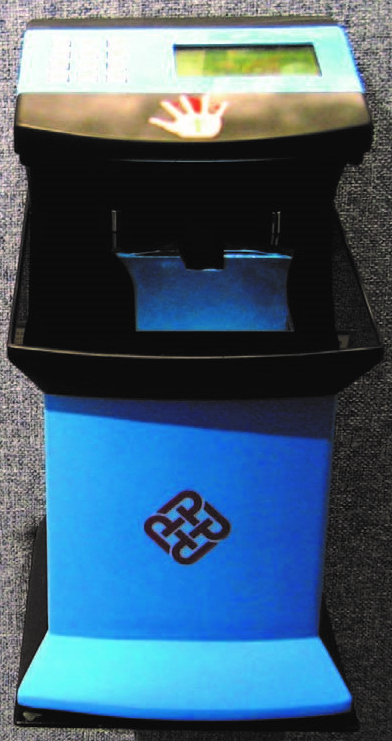
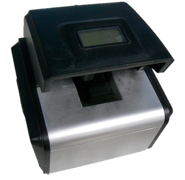
Palmprint systems with pegged flat platen surface (Kong2002, Zhang2003a, Kong2003, Wong2005, Kong2006, Hao2008, Wang2008, Kong2009, Li2009, Zhang2009, Zhang2010, Zhang2010b) have been popular in recent research. This design keeps the hand stable, avoids background interferences, captures quality images, and achieves a good recognition performance. The hand is held by the pegged flat platen surface in this kind of devices, as Fig. 2a and Fig. 2b show. The user interface platen of this kind of palmprint systems covers most area. Only the parts between the fingers are left and then protected by the upper cover. Currently the best results reported in research articles are mostly achieved in the database captured by Zhang’s device, and the EERs are summarized to be distributed from 0.267% to 0.012% (Ito2006, Hao2008, Wang2008, Zuo2008b, Guo2009a, Laadjel2009a, Guo2009, Zhang2010, Zhang2010b, Li2012a), which would be generally better than other systems’ EERs, which range from 0.26% to over 4.73% (Ong2003, Han2003, Kumar2003, Lin2005, Connie2005, Goh2006, Badrinath2007, Han et al., 2007b, Struc2008, Ong2010).
 \[ (a) \]
 \[ (b) \]
Fig. 2 Typical palmprint devices with a pegged flat platen surface. (a) PC based area palmprint device. (b) Embedded area palmprint device.
\[ (b) \]
Fig. 2 Typical palmprint devices with a pegged flat platen surface. (a) PC based area palmprint device. (b) Embedded area palmprint device.
This kind of palmprint system uses an area scan camera, which is a camera with an area scan charge-coupled device (CCD) or complementary metal-oxide-semiconductor (CMOS) sensor. When an area scan camera captures images, all pixels of a frame are captured at the same time. Then, electrons of pixels are transferred line by line to the output channel and are amplified and sent to the output port pixel by pixel.
3 Line-Scan Palmprint System Design
To take advantage of cutting-edge line-scan image sensors, we propose an online palmprint acquisition system (LPS) based on the line-scan image sensor. A synchronizing unit, which is composed of a roller module, an encoder, and an FPGA, is designed for our system. It synchronizes the motion of hands with the capturing of images of the line-scan image sensor. With this unit, the proposed system captures the palmprint adaptively to the motion of the hands in real-time. Meanwhile, the resolution and quality of images are similar as with current area systems, which enables a fair comparison of recognition performance. A control board is implemented based on an FPGA. The USB interface is utilized. With this universal interface, the proposed capturing device works with either a desktop computer or an embedded platform, which is a major advantage for next generation real-time online applications. The rest of this section starts with the line-scan imaging scheme, followed by the system framework. After the introduction of the system framework, the three hardware parts: the line-scan image sensor, the synchronizing unit, and the controller board are discussed. The working system is presented at the end of this section.
3.1 Line-Scan Imaging Scheme
In a line-scan sensor, there is only one line of pixels. Pixels in a line-scan sensor can be extended to enlarge the imaging area. With a larger imaging area, the dynamic range could be improved. This is different from area sensors. In area sensors, the size of pixels is a trade-off between resolution and dynamic range given a certain kind of pixels. In area cameras, a larger pixel could bring a higher dynamic range, but with lower resolution. This problem does not exist in line-scan sensors, as they could capture high-resolution images without compromising dynamic range.
In an imaging system, a line-scan sensor requires a much smaller space for the optical path than that an area image sensor requires, which is the most critical limitation of current palmprint capturing devices. As Fig. 3b shows, a line-scan sensor captures a line image. In a line-scan sensor imaging system, the field of view is only one pixel long in the vertical direction. Comparing to the angle of view in the horizontal direction, it is merely one of hundreds or one of thousands in the vertical direction. Therefore, in a line-scan imaging system, the optical path, which is required by the traveling of rays from the object to the sensor, is a thin plane in three-dimensional space. On the contrary, the optical path in a traditional area image sensor is a two-cone-shaped space, as Fig. 3a shows. When a line-scan sensor captures a wider object, the sensor can be used to swipe the object without increasing the optical path. However, for an area scan camera, the optical path has to be increased. In the area imaging system, optical path is critical to the field of view, which is determined by the dimensions of objects. In a palmprint acquisition system, the object is the palm. The field of view has to be large enough to cover the palm. The field of view can be extended by increasing the distance between lens and objects, or by increasing the angle of view. However, this will introduce the following problems: First, a longer distance between lens and objects brings a longer optical path, which occupies more space. Second, while the angle of view is increasing, the off-axis interference light comes into the optical system, and this could result to aberrations. The image quality could be sacrificed, thus, neither could provide a better solution. Because of the reasons mentioned above, the space taken by the line-scan sensor optical path is much smaller than the space taken by the area image sensor, which may not be further reduced without changes in the imaging structure.
 \[ (a) \]
 \[ (b) \]
Fig. 3 A comparison of optical path space between area scan image sensor based palmprint acquisition systems and line-scan image sensor based systems. (a) Area image sensor based palmprint acquisition system imaging scheme. (b) Line-scan image sensor based palmprint acquisition system imaging scheme.
\[ (b) \]
Fig. 3 A comparison of optical path space between area scan image sensor based palmprint acquisition systems and line-scan image sensor based systems. (a) Area image sensor based palmprint acquisition system imaging scheme. (b) Line-scan image sensor based palmprint acquisition system imaging scheme.
A line-scan camera device in fingerprint recognition was invented by Mil’shtein et al., which is different from the palmprint case. In this fingerprint line-scan device, the camera is rotating around the finger when capturing. The camera captures one vertical line of fingerprint image at a time until 180° of the whole finger surface is scanned. This design captures a cylindrical fingerprint image. However, it is not suitable to be applied in palmprint. The skin surface of the palm is an uneven plane, and the palmprint is not a cylinder. This structure could not be used in line-scan palmprint systems.
Though a line-scan sensor resembles a swipe fingerprint sensor, they are not the same. A swipe sensor captures a rectangle image, which is long in length and narrow in width like a bar. Bar images are matched with each other to assemble the full fingerprint image. Although swipe sensors are very successful in fingerprint application, they are not suitable for palmprint application. First, the palm is not completely flat. The middle area of the palm is too far to be captured by the swipe sensor. For example, the capacitive swipe sensor has to be touched. The ultrasonic wave-based swipe sensor gets true skin layer fingerprint in less than one-millimeter distance. When working with a long distance, the ultrasonic sensor chip generates tremendous heat. Second, silicon chips are expensive. A palm is significantly larger than a fingerprint. The larger the chips’ dimensions, the lower the conformance rate of chips. A swipe sensor customized for palmprint would not likely be economical.
When building a system based on the line-scan sensor, there is a challenge of motion synchronizing. A line-scan image sensor captures images only with the help of a scanning unit that moves the object or the sensor along the vertical direction. The benefit of this structure is that continuous images of objects could be captured, and a long or large object could be captured by a thin or small sensor. However, an extra unit, which synchronizes the movement of the sensor and the object, is required.
This synchronization problem was solved in industrial machine vision systems. In industrial machine vision systems, line-scan image sensors and cameras have been used for decades. A typical structure of an industrial line-scan system consists of a line-scan camera, a conveyor belt and a motion controller (Kim2001, Baykal2004). Objects are moving smoothly on the conveyor belt when the line-scan camera is taking line images. A motion controller monitors and adjusts the moving speed of the conveyor belt, and triggers the line-scan camera to capture images synchronously.
However, the problem is different when building an LPS, and it is still a challenge. First, in a palmprint system, the imaging object is a part of human body. The palm cannot be moved as a physical subject. The synchronizing process should be driven by the palm of people. Second, the motion of the palm cannot maintain a constant speed without any guide. Typically, the human palm moves in various speeds and directions unless instructed or guided. Third, when building a palmprint system, the user interface should be user-friendly. The motion of the palm should not be limited to a rigid way. In summary, motion synchronizing should be responsive, adaptive, and user-friendly.
3.2 System Framework
Nowadays, a biometric acquisition system is expected to have both desktop and embedded versions. Biometric applications using these acquisition systems deployed in handheld or mobile platforms are very popular (Han2007c, Jia2012, Shen2012). A framework, in which both the desktop computation platform and the embedded platform are compatible with the same image-capturing device, is proposed for our line-scan sensor based system. The framework is illustrated in Fig. 4. This framework uses an embedded controller, which regulates all the device parts and communicates with the computation platform through a universal interface. With this structure, the proposed palmprint capturing device could be used in both desktop applications and embedded applications with respective drivers. In palmprint acquisition systems, the image-capturing speed, the image quality, and the user interface design are the most important parts to achieve the goal of the proposed system.
 Fig. 4 Diagram of the system framework.
To achieve these objectives, all parts of the system should be considered, as shown in Table I.
TABLE I
KEY FACTORS RELATED TO SPEED, IMAGE QUALITY, AND USER EXPERIENCE
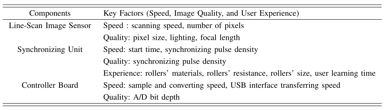
The data flow speed of the system is defined by the slowest part. Hence, each part should be optimized to maximum speed. First, the synchronizing unit should generate accurate synchronizing pulses according to the movement of the hand to minimize the lag. Second, the sensor should be fast enough for real-time image capturing to minimize the data waiting time in the buffer. The driver of the sensor should generate driver signals at a proper speed and accurate timing to minimize the lag. Third, the speed of the A/D converter should be faster than the output of the pixels. A buffer could help cache the data while waiting for transfer through the interface. With this setting, the data flow speed is only dependent on the image sensor.
To capture images with proper quality, the sensor, the optical system, and the synchronizing unit should maintain a stable and accurate resolution in both vertical and horizontal directions.
3.3 Line-Scan Image Sensor - CIS Module
A line-scan sensor is a kind of image sensor with a very simple structure (Fischer2003, Watanabe2006, Marino2007, Luna2010, Chang2012). The photodiodes are simply arranged in a linear array or a single line. Applications using line-scan sensors are designed with either the camera or object moving in a vertical direction. They are used in applications in which the object motion is under rigid control, for example, document scanning. They can be made by CCD or CMOS technology.
Instead of a traditional line-scan CCD or CMOS sensor chip, a new and highly integrated CMOS line-scan sensor module – CIS is designed for the proposed system. This CMOS line-scan sensor module is an integrated module that includes LED lights, micro lenses, and several CMOS line-scan sensors. These parts are integrated into one package, and all the control signals are pinned out through one common connector. This module is produced in a professional factory, who assures its quality by calibrating the lens, the sensor chip, and the LED lights according to our requirements. The major features are listed in Table II. This sensor is 183 mm long to enable capture of the whole hand. The vertical length of the captured area is the same as the horizontal length of the captured area, which is also 183 mm. The average hand length is 189 mm for a male and 172 mm for a female (Theaveragebody2012). The palm is typically shorter than the hand. The average hand width, which is also the width of the palm, is 84 mm for male and 74 mm for female (Theaveragebody2012). The area that the sensor captures is sufficiently larger than both masculine and feminine palms. It also covers parts of the fingers and the wrist.
TABLE II
LINE-SCAN IMAGE SENSOR (CIS MODULE) CHARACTERISTICS
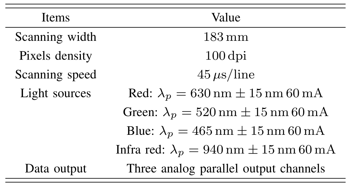
The resolution of this CIS sensor is 100 dpi, and can be configured to 200 dpi and 50 dpi. The resolution of the sensor determines the horizontal resolution of the captured image. The optimal resolution is 100 dpi according to studies of the physical resolution of palmprint features by Shu and Zhang, Zhang et al., Zhang and Shu, and Wong et al..
This CIS sensor scans at a speed of 45\( \mu s\) per line in 100 dpi mode. It captures 720 lines at a time to get the full hand image including the wrist part. Image capturing takes 33ms. This capturing speed ensures that the processing time is not delayed by the sensor. However, the entire processing time depends on the movement of hands.
After capturing an image, this CIS sensor outputs the data through three parallel channels. This structure accelerates the output in a convenient way.
This CIS module is equipped with a rod lens array (RLA). The RLA is an array of cylindrical rod lenses, which are highly polished small diameter rods made of transparent homogeneous materials. They work as cylindrical lens for the linear array CMOS sensor pixel by pixel. The typical working distance of this kind of lens is about several millimeters. In the customized module, it was 3mm (-2 mm / +4 mm).
As shown in Table II, there are four types of LEDs deployed in our CIS module, 630 nm for red, 520 nm for green, 465 nm for blue and 940 nm for infrared spectra. Typical palmprint features lay in the visible spectrum, from 380 nm to 780 nm. They make a hybrid of white with color temperature of 6500K. Recent research (Zhang2010) has discovered that multi-spectral palmprint images are better than traditional palmprint recognition using the visible spectrum only. In the proposed CIS module, near infrared LEDs are deployed with the same intensity as the white light. The combination of visible and infrared illumination is good for anti-spoofing.
3.4 Synchronizing Unit
A synchronizing unit is designed to synchronize the motion of the hand with the CIS module capturing. The synchronizing unit consists of a pair of rollers, a gear set, and a photoelectric encoder, as is shown in Fig. 5. First, when the hand rolls through the rollers, the synchronizing unit sends synchronizing pulse signals to the CIS sensor using the encoder derived by the gear set. Second, the rollers hold the hand flattened and stretched. Otherwise, the palm could touch the surface of the CIS sensor, it would squeeze and the lines and texture could be distorted. Meanwhile, the rollers keep the hand skin 2 mm \( \sim \) 4 mm above the surface. The CIS module only captures objects in a distance of 1 mm \( \sim \) 7 mm. The depth of view is limited by the micro lenses. It requires pressure to push the roller. Thus, the hand is pressing on the rollers with a moderate force. The force moves the roller, stretches the skin of the palmprint, and keeps it flattened. Third, the distance between the two rollers is minimized to avoid a large displacement of the hand skin. Also, the two rollers are made of the same size to maintain a stable motion. They are synchronized by the gear set rolling at the same angular velocity. The hand motion on these rollers is both stable and synchronized.
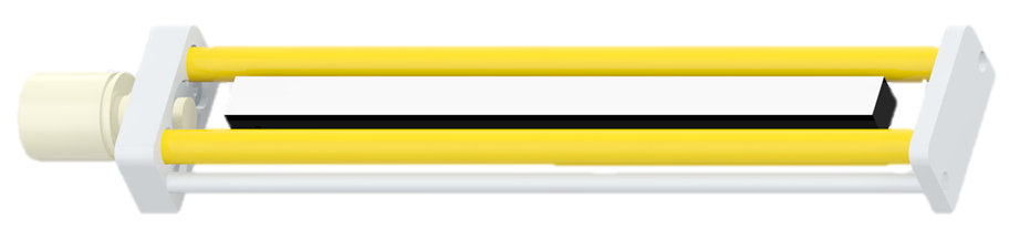 Fig. 5 CIS module and the synchronizing unit composed of a pair of rollers, a set of gears and an optical encoder.
The material of the rollers is copper. Three kinds of metal were tested in making these rollers. Neither aluminum alloy nor steel is rust-resistant. The earlier samples made from aluminum or steel were abraded by sweaty hands within a month. Eventually, copper was used for the rollers, and for over half a year, they continue to work perfectly and they retained their luster. Tiny ridges and valleys were carved in the cylindrical surface of the rollers. They ensure that the frictional force is strong enough. The movement of the rollers is driven by the hand motion.
Then the motion on the rollers is digitized by the photoelectric encoder to send out synchronizing pulses through the gear set. The image resolution on the motion direction is defined by the rollers and the gear ratio.
Given a gear ratio, \( R_g \), and the diameter of rollers, \( D_R \), when the hand moves \( M_R = \pi D_R\), the roller rotates one round. Then the axis of the encoder rotates \( R_g \) rounds. If the encoder sends out \( P_e \) pulses per round, the encoder sends out \(P = \frac{P_e}{R_g} \) pulses for \( R_g \) rounds. It means that when the hand moves \( M_R \) mm, the encoder sends out \( P \) pulses. For a filter ratio \( R_f \), the sensor only captures \( \frac{P}{R_f} \) lines, then the resolution \( S_M \) (in metric) can be computed by dividing the number of captured lines \( \frac{P}{R_f} \) by the distance \( M_R \), as follows:
\[ S_M = \frac{\frac{P}{R_f}}{M_R} =\frac{P}{M_R \cdot R_f} \]
Here, the unit of the \( S_M \) is lines per mm. One inch is 25.4 mm. Thus, the resolution \( S_L \) (in dpi) can be defined as the equation below.
\[ S_L = 25.4 \times S_M = \frac{25.4 \times P}{M_R \cdot R_f} = \frac{25.4 \times P_e}{\pi \cdot D_R \cdot R_g \cdot R_f} \]
In our prototype device, the photoelectric encoder is industry standard at 500 pulses per round (\( P_e = 500\)). The rollers’ diameter is 10mm. The gear ratio \( R_g \) is \( 2 : 1 \). The filter ratio \( R_f \) is \( 2 : 1 \). Under this condition, the vertical resolution (along the rolling direction) is 101.1 dpi, which is close to the resolution along the width direction of the CIS module (100dpi).
3.5 Controller Board
An FPGA board was built as the controller. It is composed of a CIS driver, an A/D controller, a data buffer, and a USB interface. The block diagram of the controller is shown in Fig. 6a.
 \[ (a) \]
 \[ (b) \]
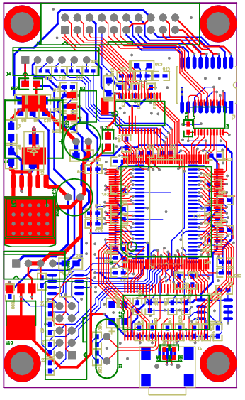
Fig. 6 The controller board of LPS. (a) Scheme block diagram. (b) Printed circuit board layout.
\[ (b) \]
Fig. 6 The controller board of LPS. (a) Scheme block diagram. (b) Printed circuit board layout.
The FPGA is the core of this board, and it controls the CIS driver, the A/D controller, and the data buffer. It receives the motion pulses and sends out driving timing pulses to the CIS module. When the CIS module is ready for one line, the FPGA lets the AD9822 A/D converter start to read analog pixel signals. Then the digitized 8-bit image signals are read and stored in the SDRAM buffer. Finally, the data are sent out through the USB interface.
Cypress USB CY7C68013A is used as the USB interface engine. It works in Slave FIFO mode for the highest transferring speed and with minimum latency. Continuous transmission speed is over 18 MiB/s in dummy data test. Both the PC-based and embedded platform-based drivers are implemented.
The printed circuit board layout is shown in Fig. 6b. The width of this PCB is the same as the width of the synchronizing unit. In this way, the width is minimized to the width of the synchronizing unit. Both the CIS module and the photoelectric encoder are powered by this board. There is only one 4-pin 12 V to 5 V power module being used here as the power supply for the entire device.
3.6 The Acquisition System
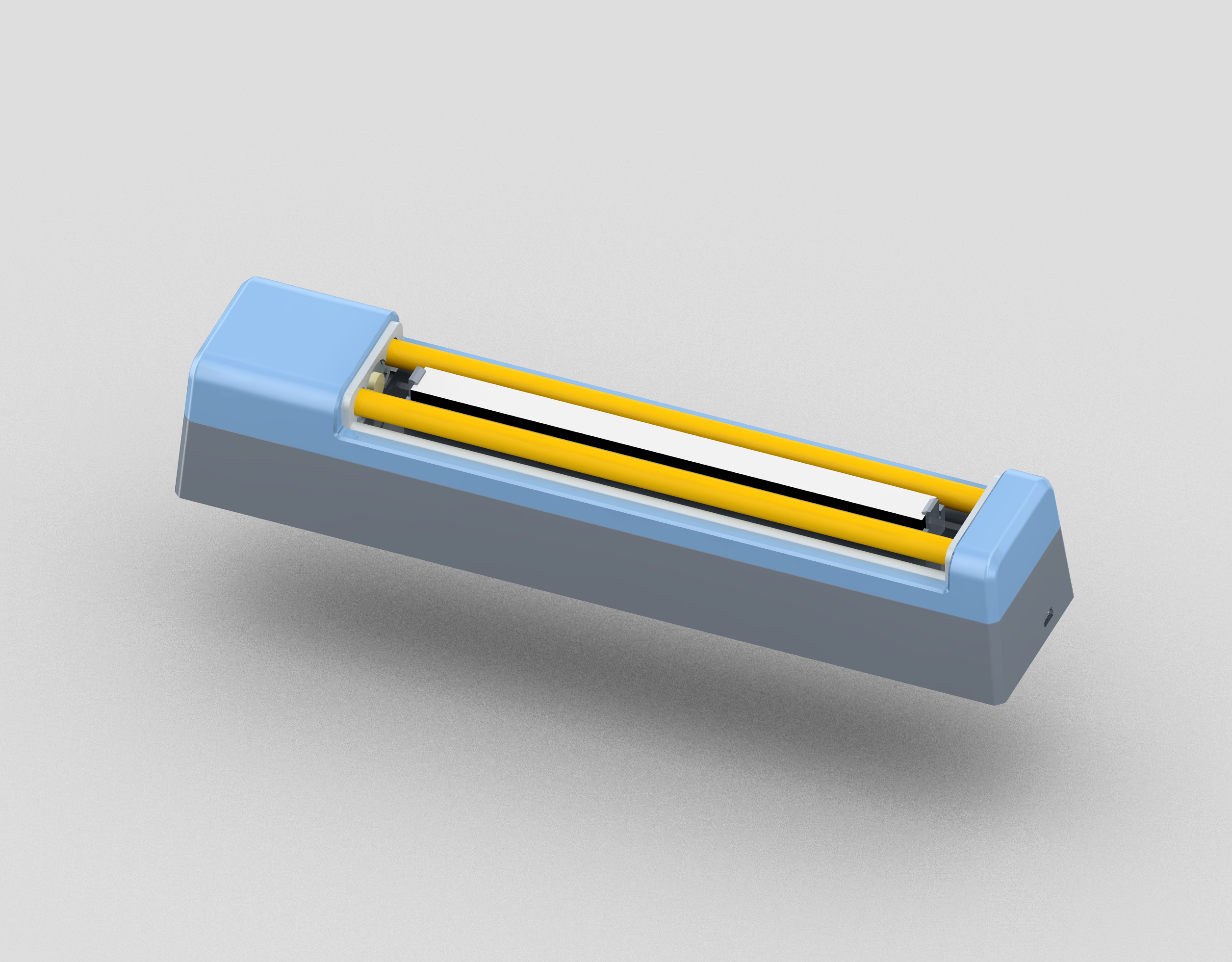
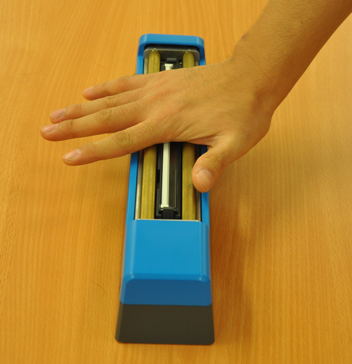
Fig. 7 shows the proposed acquisition system, which is composed of the line-scan sensor, the synchronizing unit, and the controller board. The proposed system could capture LPS images with either a desktop computer or an embedded ARM platform. The only two interfaces connected to the device are a 12 V power supply and a USB mini B plug.
 \[ (a) \]
 \[ (b) \]
Fig. 7 The proposed acquisition system. (a) The 3D design model of the acquisition system. (b) A right hand was being tested on the acquisition system.
\[ (b) \]
Fig. 7 The proposed acquisition system. (a) The 3D design model of the acquisition system. (b) A right hand was being tested on the acquisition system.
4 Experiment and Comparison
When evaluating an image acquisition system for a biometric system, the most important criterion is the recognition performance of the overall system. The requirements for acquisition systems are quite different, when the systems are being used with different feature extraction and matching methods. In this section, to compare the recognition performance of the proposed LPS and the area palmprint systems, we present a verification experiment on a large database collected by the proposed system. In this verification experiment, the proposed palmprint acquisition system is combined with a set of ROI extraction, feature extraction and matching methods to build a complete palmprint verification system. This set of ROI extraction, feature extraction, and matching methods is identical to three area palmprint systems (Zhang2003a, Wong2005, Zhang2010). In addition, the scale of the database (8000 images from 250 people) is comparable with the three area palmprint databases.
4.1 Line-Scan Palmprint Database
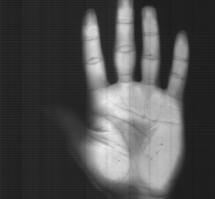
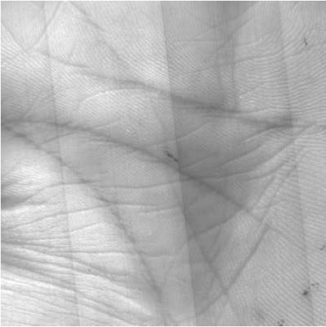
The line-scan palmprint database is built including 8000 LPS samples from 250 people. The subjects are volunteers from universities and neighboring communities. In the database, 189 people are male, and the age distribution is from 20 to 63 years old. The samples of both hands were collected from two separate sessions. Eight samples from each hand were collected in each session. The interval between the two sessions was 24.5 days on average. When collecting samples, the subject was asked to roll the rollers of the LPS device. A subject was trained for less than 30 seconds before the sampling. In this short-time training, a helper demonstrated the sampling process for two to three times, and then each subject tried for three to eight times on LPS, before the sampling in each session. Our database contains 8000 samples from 500 different palms. The resolution of the samples is \( 720 \times 720\) (100dpi). The images captured by the proposed device are shown in Fig. 8.
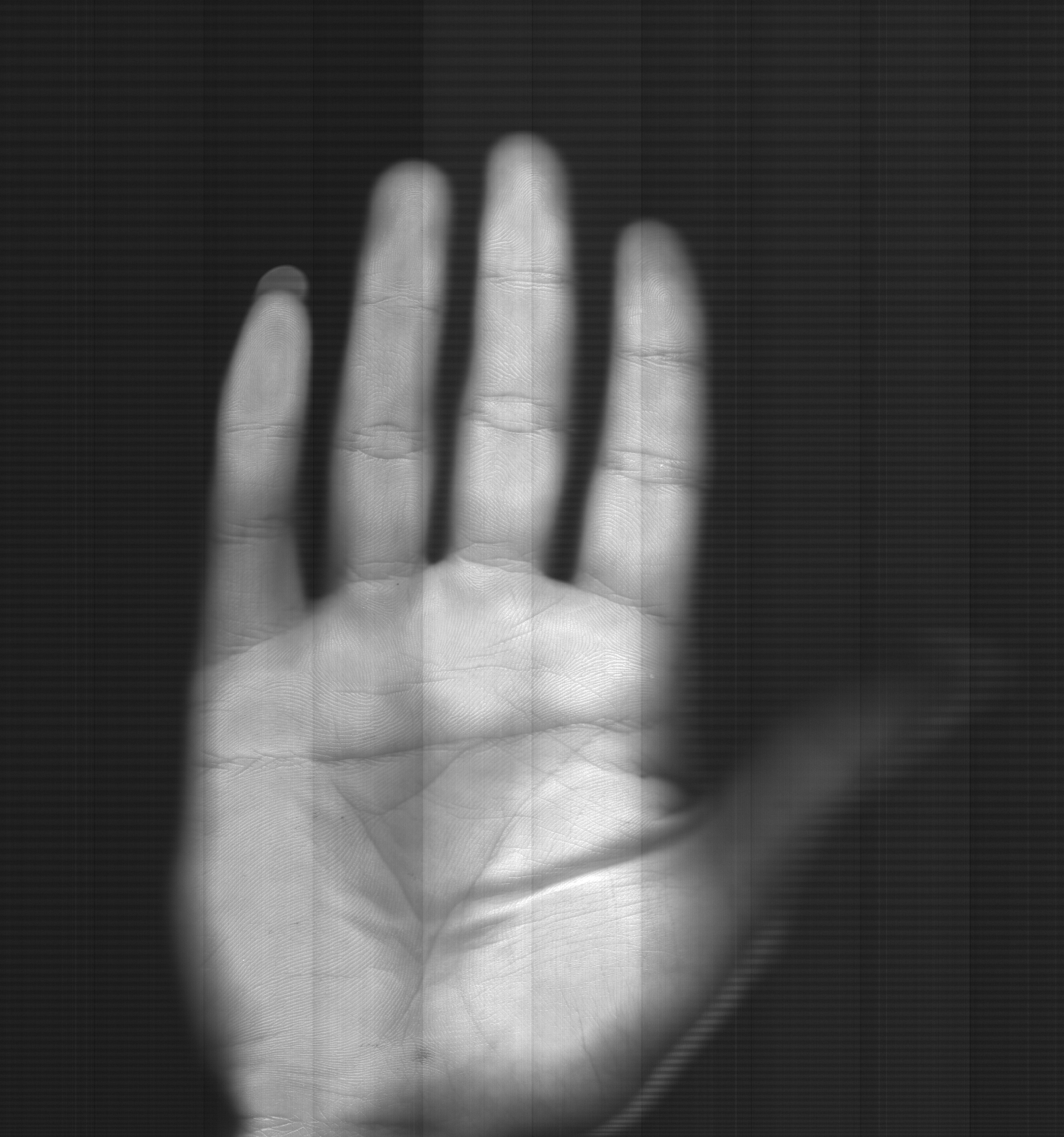 Fig. 8 The captured palmprint images.
4.2 Verification Experiment
To compare with current real-time online area based palmprint systems (Zhang2003a, Wong2005, Zhang2010), we needed the recognition performance of a verification experiment of the proposed system working in the same environment.
Fig. 9 shows the flowchart of the experiment. The experiment was designed following the area palmprint systems’ convention. This experiment consisted of four parts: image capturing, ROI extraction, feature extraction, and matching. In image capturing, the proposed LPS has been used.
 Fig. 9 LPS verification experiment flowchart.
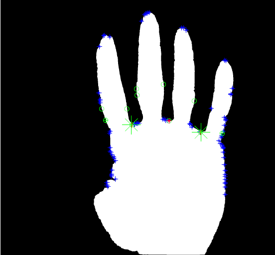
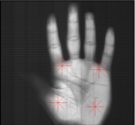
The ROI extraction method is based on the work of Guo et al.. The extraction of ROI has five steps: preprocessing, binarization, cont our extraction, finding tangent points and computing ROI location, as is shown in Fig. 10a to Fig. 10f. This ROI extraction method has been used also in Zhang2003a, Wong2005, Zhang2010.
 \[ (a) \]
 \[ (b) \]
 \[ (c) \]
 \[ (d) \]
 \[ (e) \]
 \[ (f) \]
Fig. 10 Five-step ROI extraction. (a) a palmprint sample; (b) binarization result; (c) contour extraction; (d) tangents points found; (e) located ROI; and (f) extracted ROI.
\[ (f) \]
Fig. 10 Five-step ROI extraction. (a) a palmprint sample; (b) binarization result; (c) contour extraction; (d) tangents points found; (e) located ROI; and (f) extracted ROI.
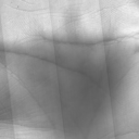
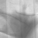
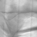
 Fig. 11 Extracted palmprint ROIs.
In feature extraction, the competitive coding scheme is implemented to extract features and to encode the features of palmprint ROIs. The competitive coding scheme (CompCode, Kong2004compcode) is a very effective 2D Gabor filter-based palmprint feature extraction method. It extracts the orientation information of palm lines. This method is widely used in area-based palmprint systems. This method is the most promising method in real-time online palmprint feature extraction study.
During matching, the Hamming distance is adopted following the best practice of area-based convention (Zhang2010), which has proven to be efficient and effective in palmprint feature matching.
With this design of the experiment, the line-scan palmprint verification system was in the identical setting as the setting of the area sensor-based ones. The verification accuracy is computed as follows: each palmprint sample is matched with all the other palmprint samples in the database. The total number of impostor matching is 31,936,000, and the number of genuine matching is 60,000. The EER, which is the point when the false accept rate (FAR) is equal to the false reject rate (FRR), is used to evaluate the accuracy.
The EER of the verification experiment is 0.048% when the FAR equals the FRR. Compared with area palmprint systems, this result is better than the results of flatbed scanner and WCBS (from 0.26% to over 4.73% (Ong2003, Han2003, Kumar2003, Lin2005, Connie2005, Goh2006, Badrinath2007, Han et al., 2007b, Struc2008, Ong2010)), and lies within the range of the pegged platen palmprint systems (from 0.267% to 0.012% (Ito2006, Hao2008, Wang2008, Zuo2008b, Guo2009a, Laadjel2009a, Guo2009, Zhang2010, Zhang2010b, Li2012a)). Although the result is not better than the best result in all area counterparts, the proposed system achieves a verification performance comparable with the best area sensor-based systems.
4.3 Comparisons with Current Area Sensor-Based Palmprint Systems
A detailed comparison with area sensor-based palmprint system is shown in Table III. The shape of LPS is 22 cm \( \times \) 5 cm \( \times \) 5 cm. Compared with current area image sensor-based palmprint acquisition systems (32 cm \( \times \) 16 cm \( \times \) 19 cm (Zhang2003a), 32 cm \( \times \) 16 cm \( \times \) 19 cm (Wong2005), 34 cm \( \times \) 28 cm \( \times \) 26 cm (Zhang2010)), the proposed system is much smaller. The volume of the proposed system is less than 6% of the volume of the area-based ones. The volume of area sensor-based systems could not be reduced further using the same imaging structure. Theoretically, the area-based design could not reduce the shape smaller than 16 cm \( \times \) 16 cm \( \times \) 20 cm, considering the space taken by the optical path and the back cover. In contrast, the shape of LPS could be further reduced after moderate improvements.
TABLE III
COMPARISON BETWEEN THE LPS AND AREA SCAN SYSTEMS
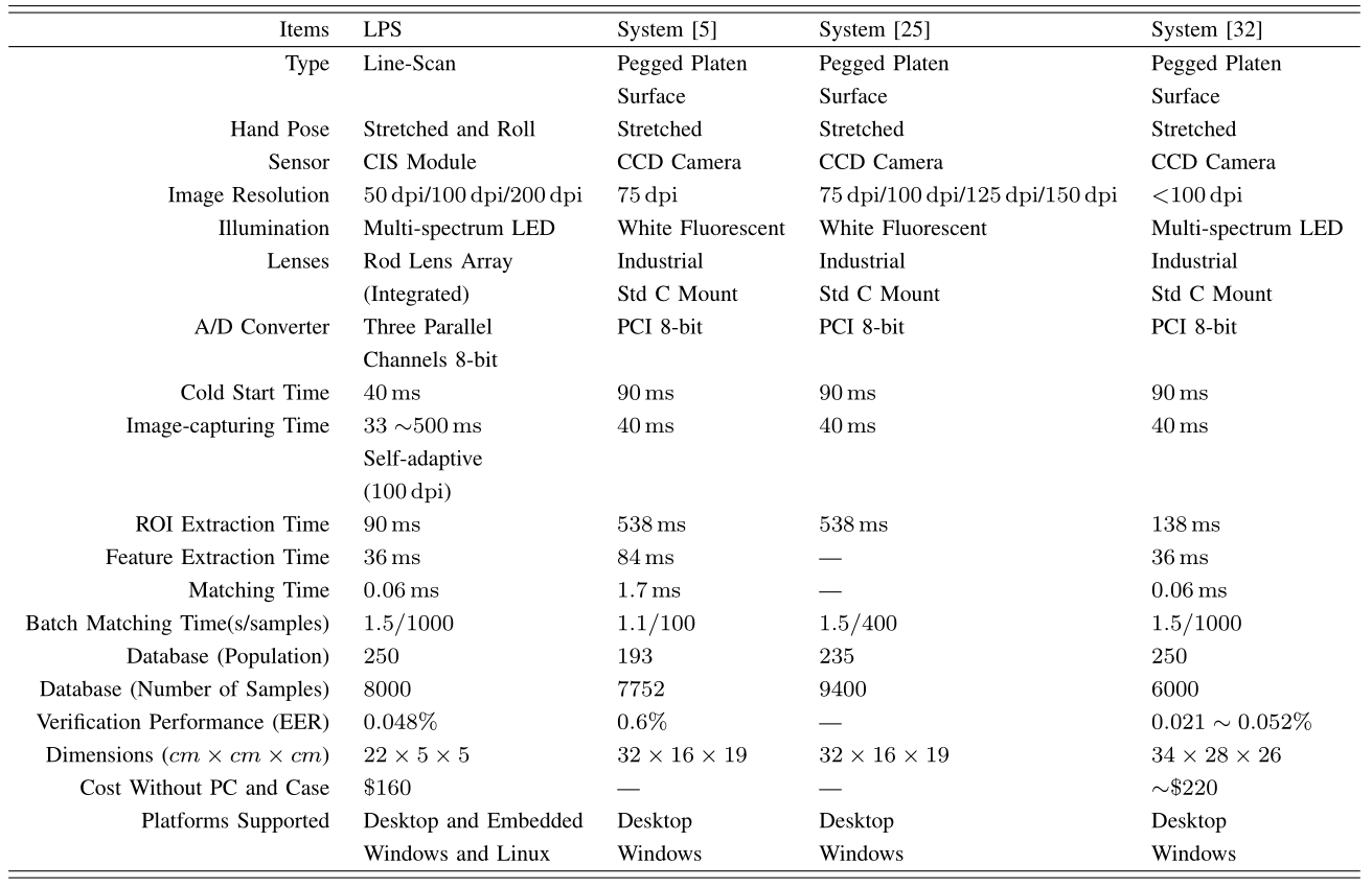
The proposed LPS with the novel synchronizing unit has improved the speed performance of the palmprint sampling process. LPS works faster than area-based ones when the hand is moving fast. More importantly, LPS captures samples according to the user’s movement. The speed of capture is self-adaptive to the user. The capture timing is synchronized to the movement of the human hand.
Fulfilling the size and speed requirements, LPS does not compromise verification performance. LPS achieves a verification performance (0.048%) comparable with most advanced area sensor-based counterparts (0.6% (Zhang2003a), 0.021% to 0.052% (Zhang2010) in terms of EER on a databases of a similar scale (8000 images). LPS does not reduce the volume by sacrificing recognition performance. Meanwhile, it further shows that palmprint recognition can achieve a similar verification performance (EER < 0.06%) in different acquisition systems.
The proposed LPS works with both a desktop application and a mobile application. The interface of the acquisition system is a USB 2.0 interface, and both Windows and Linux drivers are developed. The acquisition system can be deployed with Windows, Linux or embedded Linux. It is practical and applicable.
The applications of the proposed acquisition system are not limited to palmprint acquisition. The proposed acquisition system can be also applied to fingerprint recognition, finger inner knuckle print recognition, finger inner print recognition, finger vein recognition, hand geometry recognition, and palm vein recognition. Any combination of formerly mentioned hand biometrics and palmprint recognition can also use the proposed LPS. The proposed LPS can be applied with minor modifications in these hand biometrics. The performance of the modified system could be no worse than area based systems. Meanwhile, the volume of the system could be smaller, and mobile application could be realized.
5 Conclusion
In this paper, a novel line-scan sensor-based palmprint acquisition system is proposed to expand the application of palmprint biometrics. This LPS is featured with a customized and highly integrated line-scan sensor, a self-adaptive motion-synchronizing unit, and a cross-platform control board. The volume of the proposed system is less than 6% of the volume of current palmprint systems, without compromising verification performance. This system is suitable for online palmprint biometric applications.
Future research of LPS could go in three directions. First, with further study on optimization of the mechanical structure of the current design and using the same structure of the proposed system, an even smaller system could be made. Second, the materials and the structure of rollers could be improved. Self-cleaning materials could be used to keep the surface clean. Using more durable materials can contribute to reducing the size of the rollers. Third, motion synchronization can be integrated into the line-scan module. With moderate improvements on the synchronizing unit, the ideal size of the proposed system in mass production could be less than 15 cm \( \times \) 2 cm \( \times \) 2 cm in theory. The proposed LPS could be used in space-critical and portable situations to expand the use of palmprint recognition. Furthermore, inspired by the proposed system, more practical and applicable hand biometric systems could be invented.